Perilex, CEEform and phase rotation — recognising the wiring
This page has not yet been technically reviewed by a qualified person. Always check the current standard and your own appointment (aanwijzing); this is not a substitute for NEN 3140 or NEN 1010.
Perilex, CEEform and phase rotation
Three topics that often show up together on the job: the Perilex connector (5-pin, 3P+N+PE) for three-phase appliances such as cooking hobs, ovens and workshop machines, the CEEform connector (also called a CEE plug or "industrial plug") for three-phase connections, and phase rotation, which determines which way a three-phase motor spins.
Perilex — pin layout
The round, 5-pin (3P+N+PE) Perilex connector is the Dutch standard for three-phase appliances up to 16 A, such as cooking hobs, ovens and workshop machines, that need more power than a regular socket outlet can deliver. How the four outer contacts are wired depends on the version (see "Perilex: single-phase or three-phase version?"); the table below shows the coupled single-phase version, as commonly found on a cooker circuit in a home.
| Contact | Function |
|---|---|
| Centre pin | PE (earth) — always the middle, thickest contact |
| Two opposite pins | Line (L) — both bridged to the same phase |
| Remaining two pins | Neutral (N) — both bridged to neutral |
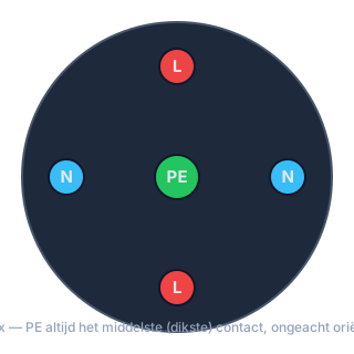
The defining feature of a Perilex connector: the centre contact is always PE, no matter which orientation the plug is inserted in — that's the whole point of the design: the earth connection cannot be reversed. The line contacts and neutral contacts are already bridged internally, so one Perilex outlet effectively delivers 2×L + 2×N + PE (sometimes used to feed two circuits — e.g. a hob and an oven — from a single connection point).
Key check before connecting: measure with a multimeter between the centre contact and the enclosure/earth bar — it must read as PE (~0 Ω to earth, no voltage present). Never swap line and PE on a Perilex connection; because of the internal bridging, that puts a lethal voltage on the connected appliance's casing.
Universal rule for every connection: PE is disconnected last and connected first. So when fitting a plug or terminal, connect PE first, then line and neutral; when removing one, disconnect line and neutral first, and PE last of all. That way earthing is always in place while there's still a chance of voltage being present.
Perilex: single-phase or three-phase version?
Not every Perilex outlet is wired the way described above. In practice you meet two configurations, and you can't tell which one you're looking at from the plug itself:
| Version | Wiring | Typically found |
|---|---|---|
| Single-phase, coupled | Two of the four outer contacts bridged internally to the same phase, the other two to neutral (as above) — fed from two coupled single-phase final circuits whose disconnecting mechanisms are mechanically linked | Most common for a cooker circuit in a residential installation |
| Three-phase, 4-wire | All four outer contacts wired separately: three to their own line (L1, L2, L3), one to neutral — fed from one 4-pole final circuit | Found on heavier cookers/appliances that genuinely draw three-phase power |
You determine which version you're dealing with by measuring the voltage between every pair of the four outer contacts (on the actual live supply, after energising, and with the applicable safety measures in place):
- All readings are 0 V or ~230 V, never ~400 V → single-phase version (the two 0 V pairs are the bridged line and neutral contacts).
- At least one pair reads ~400 V → three-phase version (that pair is two different lines); the remaining pairs then show a mix of ~230 V (line-to-neutral) and ~400 V (line-to-line).
Note — training voltage versus mains voltage: the values ~230 V / ~400 V apply to a real installation. On a training rig with reduced voltage (e.g. 23/40 V) you read the same ratio: phase–phase = √3 × phase–neutral. Judge the ratio, not the absolute number.
On a coupled single-phase Perilex circuit, the disconnecting mechanisms of the two underlying final circuits are linked — switch one off and the other switches off with it. Never rely on the diagram alone for this: before making the circuit dead, always demonstrate yourself that both poles are actually disconnected, because a mechanism that isn't (properly) linked will otherwise leave half the connector live.
Reading single-phase vs three-phase from the diagram
Before you ever measure anything, most installations can already be identified from the diagram's notation:
| Notation | Meaning |
|---|---|
| 2P+2N or 1P+N | Single-phase: 1 line conductor + neutral (+ PE drawn separately) |
| 3P+N or 4P | Three-phase: 3 line conductors + neutral (+ PE) |
| 3P (no N) | Three-phase without neutral — only between the phases (400 V line voltage), common on large motors |
Count the conductors drawn on the diagram before opening the enclosure: 2 conductors points to single-phase, 4 conductors (3L+N) to three-phase with neutral, 3 conductors without N to a motor feed with no neutral.
CEEform / CEE connector — pinout
The CEEform connector has a fixed, standardised layout (IEC 60309). The clock position of the earth pin (PE) and the pin layout vary by voltage class (see table below); the exact coding is laid down in the standard. For the two classes most common in the Netherlands — blue (single-phase 230 V) and red (three-phase 400 V) — the earth pin sits at the 6 o'clock position (at the bottom, between the other pins).
| Housing colour | Voltage/current | Pin layout |
|---|---|---|
| Blue | 230 V, single-phase (16/32 A) | L, N, PE (PE at 6 o'clock) |
| Red | 400 V, three-phase (16/32/63/125 A) | L1, L2, L3, PE (+ N on the 5-pin version, PE always at 6 o'clock) |
| Yellow | 110 V (site/construction supply) | L, N, PE |
Full colour/clock-position code by voltage class (the clock position in the table is the earth pin's (PE) position; for a given plug always check colour, voltage and number of poles — blue and red both have PE at 6 o'clock, so the pin position alone does not tell them apart):
| Voltage class | Colour | Earth pin (PE) clock position |
|---|---|---|
| 20–25 V | Violet | 10 o'clock |
| 40–50 V | White | 10 o'clock |
| 100–130 V | Yellow | 4 o'clock |
| 200–250 V | Blue | 6 o'clock |
| 380–480 V | Red | 6 o'clock |
| 500–690 V | Black | 7 o'clock |
The clock position of the earth pin is one of the features the standard uses to tell voltage classes apart, but not the only one. Never rely on the pin position alone: always check colour, voltage and number of poles.
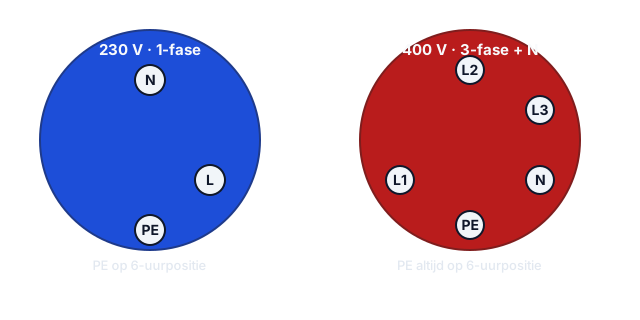
On the 5-pin red CEE plug (three-phase + N + PE), the line pins sit at fixed positions around the clock face — which lets a phase-rotation tester or draaiveldmeter check the rotation direction directly, without needing to swap the plug around.
Identifying unknown contacts by measurement
If the wiring can no longer be reliably traced from the colour code — for example after a repair by someone else, or when in doubt — you establish L1/L2/L3/N by measuring the voltage between every pair of the four non-PE contacts (you already know PE: always at 6 o'clock):
- ~400 V between a pair → both contacts are line, and different from each other (L-L).
- ~230 V between a pair → one contact is line, the other neutral (L-N).
- Unlike Perilex, neutral has no second contact it reads 0 V against — each of the three line contacts therefore reads ~230 V to neutral and ~400 V to the other two line contacts.
Note — training voltage versus mains voltage: the values ~230 V / ~400 V apply to a real installation. On a training rig with reduced voltage (e.g. 23/40 V) you read the same ratio: phase–phase = √3 × phase–neutral. Judge the ratio, not the absolute number.
With three to six measurements you can unambiguously label all the contacts on a 5-pin CEE plug this way, even without documented wiring. The actual L1-L2-L3 order (and hence the direction of rotation) is then determined with a phase-rotation meter, not from this voltage measurement alone.
Phase rotation (draaiveld) — why it matters
A three-phase motor spins clockwise or counter-clockwise depending on the order L1-L2-L3 are connected. Swap two phases and the motor spins the other way — for a pump, fan or conveyor that can cause damage or an unsafe situation.
Test instruments:
| Instrument | Test voltage | Use |
|---|---|---|
| Phase-rotation indicator / phase-sequence tester (draaiveldmeter) with disc/lamps | Mains voltage present (the supply must be live) | Determines the phase sequence (clockwise/counter-clockwise) on a live supply; gives no reading on a de-energised circuit |
| Duspol / installation tester with phase-rotation function | Full mains voltage 230/400 V | Measures on the actual supply voltage; requires the circuit to already be live |
| Test plug with phase-rotation indication | Full mains voltage | Quick check at CEE connection points on construction sites |
The phase sequence (draaiveld) can only be determined on a live supply with a phase-rotation/phase-sequence tester; on a de-energised circuit such an instrument gives no reading. So check it only after the circuit has been energised, with the full set of precautions in place (PPE, release of the installation). The rotation direction of a motor is checked with the phase-rotation tester on the supply (step above) and at the trial start — not by turning the shaft by hand. On a training set-up, low voltages are often used (e.g. 23/40 V); that is a property of the set-up, not of the instrument. So read the ratio, not the absolute number: phase–phase is always √3 (≈ 1.73) × phase–neutral. 23 V and 40 V (or 230 V and 400 V) mean the same thing, and a reading on a low-voltage set-up says nothing about the voltage on a real installation. Always record the value you actually measure.
Display convention per instrument brand: a Fluke 1650/1660-series installation tester shows the result as text — "1-2-3" for clockwise, "3-2-1" for counter-clockwise, and three dashes "---" for an ambiguous or missing connection. A Profitester (Gossen Metrawatt) shows the same result not as a digit sequence but as a rotation-direction arrow on the screen. If you're not certain of your own instrument's display, first check it on a known, correctly-connected reference group to learn which symbol corresponds to which rotation direction before interpreting a result on an unknown group.
Practical sequence for a new three-phase connection
- Read the diagram: confirm it's a three-phase connection (3P+N or 3P).
- Connect L1, L2, L3, N and PE according to the colour code (brown/black/grey for line, blue for N, green-yellow for PE) and according to the diagram — don't swap conductors on your own judgement.
- Check the phase rotation with a phase-rotation tester on the live supply (motor not yet connected; observe the applicable safety measures) before ever starting the motor for the first time.
- Connect the motor (supply de-energised first), energise and briefly verify the rotation direction of a three-phase motor (test start) before it's put under load.
- If the direction is wrong: swap two phases only (never touch or swap N or PE) and repeat the check. On a plug connection this can also be done with a phase-reversing plug (fasewisselstekker) — an in-line adapter that internally crosses two phases, so you don't have to disconnect and re-terminate two conductors by hand every time.
Further reading
- PracticalUpgrading a connection — the application procedure with the grid operator
- PracticalPt1000 3-wire connection for climate control
- §411 / NEN 1010Recognising missing earth in older installations — why an earth pin is not proof
- PracticalHeat pump — electrical connection in practice
- Guard-aansluiting (isolatietest)Guard terminal in insulation resistance testing — excluding surface leakage current
- IEC 61000-4-7 / IEEE C57.110Measuring harmonics in practice — power quality analyzer, THD-I/THD-V and K-factor transformer derating